

SHAPE \* MERGEFORMAT
March 2022

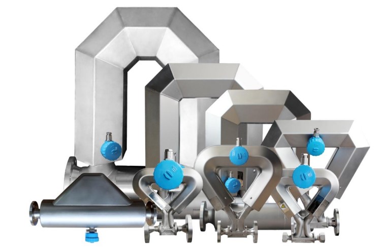
BF80 Coriolis Mass Flowmeters
■ Best measurement performance on liquid mass flow, and density measurements
■ First-in-class gas mass flow measurement
■ Excellent design to reduce installation cost and eliminate daily maintenance
BEST FIT- FOR- APPLICATION
■ Wide range of meter size from DN3 to DN200
■ Superior applications for hygienic, cryogenic, high pressure and high temperature
■ Broad range of I/O outputs and expansive communication protocols
|
|
![]()
![]()
l Direct mass flow measurement without the influences of density, viscosity, temperature and pressure
l The best flow solutions for high pressure and cryogenic applications
l Wide turndown of up to 50:1
l Modular transmitter design with more functional options
l Integrated sensor design with explosion-proof and anti-corrosion features
l The industrial process control requirements for high accurate mass flow measurement
l Ex certification
The Coriolis mass flowmeter is based on the principle of Coriolis effect. The flowmeter directly measures mass flow, density, and temperature and calculates volume flow, total flow, and fluid composition in real-time.
As shown in the following two pictures, the two flow tubes are forced to oscillate and then produce sine waves by an external exciter. When no fluid flows through the tubes, the vibration of the tubes won’t produce a phase shift between them. When fluid flows through the tubes, the tubes will be twisted to produce a phase shift by the so called Coriolis forces. The mass flow rate is directly proportional to the phase shift of the waves.
No Flow Flow Through
The flow tubes are vibrated at their resonance frequency. The fluid mass changes inside the tubes will result in the corresponding changes in the tube resonance frequency. The frequency changes can be used to calculate the fluid density.
Process temperature is directly measured by the temperature sensor that is sticky on one of the two tubes. The measured temperatures can be used to compensate temperature influences on the material elasticity to improve the accuracy of all other measurements.
BF80 mass flowmeter is now being used to measure liquid, gas or slurry in the most complex and challenging environments. The flowmeter is widely applied in process measurement and custody transfer due to the advantages of short response time, high precision measurement, and less daily maintenance.
|
Fluid |
Typical Application |
Industry |
|
l Liquid l Gas l Slurry |
n Custody Transfer n Reactor Feed Ratio n Density Measurement n Batch Control |
u Chemicals u Pharmaceuticals u Food & Beverages u Power Plant u Machinery u Pulp & Paper u Minerals & Ming u Water u Oil & Gas u Waste Water |
Example One: A BF80 mass flowmeter is installed in a truck-loading cryogenic system for batch operation.
Example Two: BF80 mass flowmeters are installed inside a chemical plant for the raw chemical material process measurement.
Example Three: A BF80 mass flowmeter is installed in a gas station for the fuel measurement.
SHAPE \* MERGEFORMAT ![]()
|
Accuracy |
Liquid: ±0.10%, ±0.15%, ±0.20%, and ±0.50% Gas: ±0.50%, ±0.75%, and ±1.0% |
|
Repeatability |
±0.05% |
|
Density Accuracy |
±0.002g/cm3 |
|
Process Temperature |
±1℃ |
|
Ambient Temperature |
-40 to +55℃ |
|
Relative Humidity |
≤95%, non-condensing |
|
Process Fluid |
Gas, liquid and slurry |
|
Case Material |
304 |
|
Flow Tube |
316L, Hastelloy C276 |
|
Transmitter Housing |
Cast aluminum alloy with epoxy polyurethane coatings |
|
Power Supply |
85 to 265VAC, 50/60Hz; 12 to 24VDC, ±5℅ |
|
Power Consumption |
Typical 5 watts, Max. 10 watts |
|
Signal Output |
Analog: 4 to 20mA, Pulse/Frequency: 0 to 10kHz |
|
Digital Communication |
Modbus RTU over RS485 by default; HART communication as an option |
|
Variables |
Mass Flowrate, Volume Flowrate, Mass Total, Volume Total, Temperature, Density, Standard Flowrate, and Standard Total |
|
Ambient Temperature |
-40 to +55℃ |
|
Conduit Connection |
M20*1.5 by default, 1/2-inch NPT female as an option |
SHAPE \* MERGEFORMAT
![]()
|
Nominal Line Size |
Max Flowrate (kg/h) |
|
DN3 |
110 |
|
DN6 |
1,200 |
|
DN15 |
3,000 |
|
DN20 |
7,200 |
|
DN25 |
12,000 |
|
DN40 |
32,000 |
|
DN50 |
60,000 |
|
DN80 |
180,000 |
|
DN100 |
300,000 |
|
DN150 |
600,000 |
|
DN200 |
1,200,000 |
![]() Accuracy and Repeatability on Liquids and Slurries
Accuracy and Repeatability on Liquids and Slurries
|
Performance Specifications |
Option 1 |
Option 2 |
Option3 |
Option 4 |
|
Mass Flow Accuracy |
±0.10% |
±0.15% |
±0.20% |
±0.50% |
|
Mass Flow Repeatability |
±0.05% |
±0.075% |
±0.1% |
±0.25% |
|
Density Accuracy |
±0.002g/cm3 |
|||
|
Density Repeatability |
±0.001g/cm3 |
|||
|
Temperature Accuracy |
±1℃ |
|||
![]() Accuracy
and repeatability on gases
Accuracy
and repeatability on gases
|
Performance Specifications |
Option 1 |
Option 2 |
|
Mass Flow Accuracy |
±0.50% |
±0.75% |
|
Mass Flow Repeatability |
±0.25% |
±0.35% |
|
Temperature Accuracy |
±1℃ |
|
|
Temperature Repeatability |
±0.2℃ |
|
SHAPE \* MERGEFORMAT
![]()
Zero stability is defined as the flow rate that approaches to the low end of flow range where the
flowmeter accuracy begins to deviate from the normal accuracy ratings. The descriptions about the zero stability can be found in the next section. When the flowmeter operates at the low end of flow range, the accuracy begins to deviate from the normal accuracy rating. In this case, the meter accuracy can be calculated by: ±accuracy ± [(zero stability/flow rate)×100]%
Zero stability is usually measured in the laboratory and can be used to calculate the expected sensor accuracy. Under zero flow laboratory conditions, the average flowrate measured by the calibration system should be within the range defined by the sensor’s zero stability value (0 ± zero stability). Each sensor has a unique zero stability. By statistics, about 95% of the flowrate should be within the range of the zero stability.
|
Nominal Line Size |
Zero Stability (kg/h) |
|
DN3 |
0.01 |
|
DN6 |
0.03 |
|
DN15 |
0.09 |
|
DN20 |
0.23 |
|
DN25 |
0.23 |
|
DN40 |
0.70 |
|
DN50 |
0.93 |
|
DN80 |
2.92 |
|
DN100 |
9 |
|
DN150 |
15 |
|
DN200 |
25 |
Turndown ![]() The following one
graph and one table show an example of the measurement characteristics under
various flow conditions. As shown in the graph, when the turndown is greater
than 20:1, the meter accuracy begins to devastated dramatically.
The following one
graph and one table show an example of the measurement characteristics under
various flow conditions. As shown in the graph, when the turndown is greater
than 20:1, the meter accuracy begins to devastated dramatically.
A. Accuracy, %
SHAPE \* MERGEFORMAT ![]()
B. Flowrate, % of nominal
The following table shows accuracy and pressure drop across flowrate for a typical 50A sensor:
|
Turndown from Nominal Flow Rate |
20:1 |
15:1 |
10:1 |
1.5:1 |
1:1 |
|
Accuracy (±%) |
0.14 |
0.10 |
0.10 |
0.10 |
0.10 |
|
Pressure Drop (MPa) |
0.00 |
0.00 |
0.02 |
0.10 |
0.23 |
|
Measurement Unit |
g/cm3 |
kg/m3 |
|
Accuracy |
±0.002 |
±1 |
|
Repeatability |
±0.0005 |
±0.5 |
|
Measurement Range |
0.2 to 3 |
200 to 3,000 |
Temperature Performance ![]() Sensors can be used in the temperature ranges shown in the
temperature limit figures. When selecting transmitter options, temperature
limit figures should be used as one of the general guides. If the application
conditions are close to the shaded area, we recommend the customers to consult
with our local Reliant Instruments representatives.
Sensors can be used in the temperature ranges shown in the
temperature limit figures. When selecting transmitter options, temperature
limit figures should be used as one of the general guides. If the application
conditions are close to the shaded area, we recommend the customers to consult
with our local Reliant Instruments representatives.
l In all cases, the transmitter cannot be operated where the temperature is below –40°C or above +60°C. If a sensor is to be used where the temperature is out of the allowed range, the transmitter must be moved to the locations where the temperature is within the allowable range.
l Temperature limits may further be restricted by other hazardous conditions. Refer to the hazardous approval documentation for detailed information. The document is usually shipped with the sensor or can be downloaded at www.reliantinstruments.com
l The transmitter can be remotely mounted. The remote flowmeter allows the sensor case to be insulated without covering the meter or the sensor junction box. When insulating the sensor case at the elevated process temperatures (above +60°C), please ensure that the transmitter will not be enclosed in the insulation as this may lead to transmitter failure
|
Temperature Accuracy |
All models |
±1℃ |
|
Temperature Limits |
All models |
See the figures below |

CNG Mass Flowmeter
|
Process Temp Limits |
Common Mass Flowmeter |
-196 to +280℃ |
|
CNG Mass Flowmeter |
-30 to +80℃ |
|
|
Ambient Temp Limits |
Storage |
-50 to +65℃ |
|
Operation |
-40 to +55℃ |
As shown in the following figure, a group of temperatures from T6 to T1 refers to the maximum process temperature in which the sensor operates at the ambient temperature of 45 ℃.

Sensor maximum working pressure reflects the highest possible pressure rating for a given sensor. Process connection type and environmental and process fluid temperatures may reduce the maximum rating.
|
Nominal Line Size |
Maximum Working Pressure (MPa) |
|
|
Common Models (MPa) |
High Pressure Models (MPa) |
|
|
DN3 |
4.0 |
25 |
|
DN6 |
4.0 |
25 |
|
DN15 |
4.0 |
25 |
|
DN20 |
4.0 |
25 |
|
DN25 |
4.0 |
25 |
|
DN40 |
4.0 |
25 |
|
DN50 |
4.0 |
25 |
|
DN80 |
4.0 |
25 |
|
DN100 |
4.0 |
25 |
|
DN150 |
4.0 |
25 |
|
DN200 |
4.0 |
25 |
Case Pressure ![]() Sensor cases can realize secondary pressure resistance and
protection, so as to prevent serious accidents caused by dangerous fluid
leakage to the external environment. Implement China’s GB/T 20801 code for
pressure piping, industrial piping, and GB 50316 code for design of industrial
metal piping, process piping code and other
standards.
Sensor cases can realize secondary pressure resistance and
protection, so as to prevent serious accidents caused by dangerous fluid
leakage to the external environment. Implement China’s GB/T 20801 code for
pressure piping, industrial piping, and GB 50316 code for design of industrial
metal piping, process piping code and other
standards.
|
Nominal Line Size |
Case Max Pressure (MPa) |
|
DN3 |
3.1 |
|
DN6 |
3.1 |
|
DN15 |
2.9 |
|
DN20 |
2.5 |
|
DN25 |
2.1 |
|
DN40 |
2.0 |
|
DN50 |
1.8 |
|
DN80 |
1.5 |
|
DN100 |
1.3 |
|
DN150 |
1.1 |
|
DN200 |
1.0 |
BF80 mass flowmeter has been granted the EX certificate from Test Centre of China Coal Research Institute (CCRITC) in early 2022. The details please find the followings:
|
Ex-mark |
Ex d ia IIC T6 Gb |
|
Ex Certificate No. |
CCRI 21.1473X |
|
Enclosure Rating |
IP67 |
Unit: mm Error: ±2mm Flange Standard: DIN2635 PN40
 TR Transmitter
Remote-mount Transmitter
Compact-mount Transmitter
SHAPE \* MERGEFORMAT
Ω-sharp Sensors, size from
DN3 to DN40
![]()

|
Sensor |
Size |
Dimensions (mm) |
|||
|
A |
B |
C |
D |
||
|
Ω |
DN3 |
161 |
319 |
235 |
160 |
|
Ω |
DN6 |
161 |
319 |
235 |
160 |
|
Ω |
DN15 |
188 |
339 |
293 |
162 |
|
Ω |
DN20 |
199 |
401 |
301 |
101 |
|
Ω |
DN25 |
210 |
539 |
448 |
203 |
|
Ω |
DN40 |
262 |
636 |
576 |
227 |
|
Sensor |
Size |
Dimensions (mm) |
|||
|
A |
B |
C |
D |
||
|
U |
DN50 |
552 |
711 |
506 |
20 |
|
U |
DN80 |
731 |
893 |
653 |
278 |
|
U |
DN100 |
755 |
1162 |
709 |
345 |
|
U |
DN150 |
1020 |
1322 |
907 |
393 |
|
U |
DN200 |
1200 |
1600 |
1000 |
420 |
SHAPE \* MERGEFORMAT
Little-bent Sensors, Size from DN15, DN25 and DN50
![]()
|
Sensor |
Size |
Dimensions (mm) |
||
|
A |
B |
C |
||
|
Little-bent |
DN15 |
446 |
409 |
174 |
|
Little-bent |
DN25 |
580 |
426 |
174 |
|
Little-bent |
DN50 |
880 |
713 |
174 |
Sensor Installation
![]() Sensor installation is
crucial for the performance of a mass
flowmeter. In general,
the meter flow tube should be always filled with the process fluid
to prevent other
medias during the installation.
Sensor installation is
crucial for the performance of a mass
flowmeter. In general,
the meter flow tube should be always filled with the process fluid
to prevent other
medias during the installation.
SHAPE \* MERGEFORMAT
CAUTION

l Ensure that sensor explosion-proof rating, enclosure rating, and process &
ambient temperature limits which are marked on the nameplate meet or exceed the application requirements;
l When a sensor installed horizontally or vertically, the fluid flow direction must be the same as the “Arrow” indicator on the sensor body;
l When flagpole installation is adopted, the fluid flow direction must be from bottom to top;
l The sensor must be mounted on a firm base plate or with flanges.
|
Inverted Installation for Liquid |
|
Upright Installation for Gas |

|
l Upright installation is recommended if the process fluid is a liquid because the leftover process fluid can be easily vaporized. Upright installation prevents the accumulation of vapor or air in the sensor tubes
l Inverted installation is recommended if the process fluid is a liquid with entrained solids, or if the process fluid is a gas which may condense. Inverted installation prevents higher density media from accumulating in the flow tubes
l Flagpole installation is recommended if the process fluid is a slurry mixture, or if the pipe is to be purged with gas or steam. Flagpole installation is a compromised method for the slurry.
SHAPE \* MERGEFORMAT
![]()
For the remote mass flowmeter, it’s strongly required to use the dedicated 9-wire shielded signal cable to connect the sensor with the transmitter at the installation place. Before conduct the signal cable wiring, please fully understand the wiring terminals in the transmitter and in the Junction Box respectively.
l Must use the dedicated 9-wire shielded cable for the signal wiring. This cable is provided by the manufacturer;
l Default length of this cable is 3m. The cable can be extended up to 100m.

|
SHAPE \* MERGEFORMAT ![]()
|
Code |
R+ |
R- |
PE |
L+ |
L- |
|
Color |
White |
Yellow |
Black (Shield) |
Gray |
Purple |
|
Description |
Right Pickoff |
Left Pickoff |
|||
|
Code |
TPE |
S2 |
S1 |
C1 |
DPE |
D- |
D+ |
|
Color |
Black (Shield) |
Black |
Green |
Orange |
Black (Shield) |
Red |
Blue |
|
Description |
Temperature Sensor |
Drive Coil |
|||||
Wiring terminals diagram in the Junction Box ![]()
|
Code |
L- |
L+ |
R- |
R+ |
|
Color |
Purple |
Gray |
Yellow |
White |
|
Description |
Left Pickoff |
Right Pickoff |
||
|
Code |
D- |
D+ |
TPE |
S2 |
S1 |
C1 |
|
Color |
Red |
Blue |
Black (Shield) |
Black |
Green |
Orange |
|
Description |
Drive Coil |
Temperature Sensor |
||||
Example: BF80 15A L 3 S M L
TR 1 A 1 M - A C 1 NN NNN
|
Item |
Code |
Code Description |
|
|
Flowmeter |
BF80 |
BF80 Mass Flowmeter |
|
|
Sensor (size + type) |
XA |
3A/6A/15A/20A/25A/40A/50A/80A/100A/150A/200A Please note: “A” type - Common type |
|
|
XB |
15B/20B Please note: “B” type - Special type applied for measuring CNG |
||
|
XM |
15M/25M/050M Please note: “M” type - Little bent type |
||
|
Pressure Rating |
L |
4MPa |
|
|
M |
25MPa |
||
|
T |
Special pressure rating on request |
||
|
Accuracy |
1 |
±0.10% |
|
|
2 |
±0.15% |
||
|
3 |
±0.20% |
||
|
4 |
±0.50% |
||
|
5 |
±0.75% |
||
|
Process Temperature |
S |
Normal temp: -70 ~ +160℃ |
|
|
L |
Ultra low temp: -200 ~ +60℃ |
||
|
H |
Ultra high temp: -40 ~ +300℃ |
||
|
Process Connection |
M |
Thread |
|
|
F |
Flange:Please specify the flange standard |
||
|
N |
No connection needed |
||
|
T |
Special process connection on request |
||
|
Flow-tube Material |
L |
316L Stainless Steel |
|
|
H |
Haste-lolly C276 |
||
|
T |
Special material on request |
||
|
Transmitter |
TR |
Round transmitter |
|
|
Display |
0 |
Without display |
|
|
1 |
With display: English display by default and other language display on request |
||
|
Power Supply |
A |
85~250VAC |
|
|
D |
24VDC |
||
|
T |
Please specify if other power supply applied |
||
|
Communication & Signal Output |
1 |
Freq/Pulse + Modbus RS485 |
|
|
2 |
4-20mA (Positive) + Freq/Pulse + Modbus RS485 |
||
|
3 |
2*4-20mA (Positive)+ Freq/Pulse + Modbus RS485 |
||
|
4 |
HART + Freq/Pulse + Modbus RS485 |
||
|
Conduit Connection |
M |
M20*1.5 by default, with no gland |
|
|
P |
1/2-inch NPT female, with no gland |
||
|
N |
ATEX / IECEx approved |
||
|
T |
Other conduit connection on request |
||
|
Separator |
- |
Flowmeter options follow up after this |
|
|
Meter Type |
A |
Remote type: The default cable length is 3 meters and other length needs to specified. |
|
|
B |
Compact type |
|
Ex Certificate |
C |
Chinese Ex certificate |
|
|
G |
ATEX / IECEx certificate |
||
|
T |
Other Ex requirement needs to be specified |
||
|
Protection Rating |
1 |
IP65 |
|
|
2 |
IP67 |
||
|
Others |
N |
Flow range: No other flow range is specified. The pattern approval flow range is the default, |
|
|
N |
Transmitter Housing: No customization is required. The default type is acceptable. |
||
|
N |
Sensor Junction Box: No glue filling by default. If necessary, please specify |
||
|
N |
Heat Insulation: No heating insulation by default. If necessary, please specify |
||
|
N |
Accessories: No accessories required. If necessary, please specify |
Suite 601, 1090 Century Avenue, Cimic Tower Pudong New Area, Shanghai 200122, China Tel: (+86) 21 5836 5336
Fax: (+86) 21 5055 0005
Mobile: (+86) 150 2165 6074
Web: www.boocca.com
![]() Email: frank.huang@boocca.com
Email: frank.huang@boocca.com
Copyright©2022 Boocca Measurement & Control Technologies (Shanghai) Co., Ltd.
All rights reserved
The BOOCCA logo is a trademark and service of Boocca Measurement & Control Technologies (Shanghai) Co., Ltd.
For the most updated version, please visit our website at www.boocca.com Specifications are subject to change without notice.
